Multiport USB-C Charger Safety Features Explained
A multiport USB-C charger uses safety features as built-in protections that help control electrical load, heat, and charging behavior across more than one connected device. Charger safety depends on the charger design, the connected device, the USB-C cable, and the charging environment working within suitable limits.
When a GaN charger fast charges a laptop, phone, or tablet at the same time, USB-C PD power negotiation helps match the requested voltage and current limit to what the device and port can accept. Voltage control, current control, heat control, cable rating, connector condition, and compliance markings all affect how safely that charging session may behave. A mismatch, damaged cable, poor ventilation, or unclear rating can increase heat risk even when the charger includes safeguards.
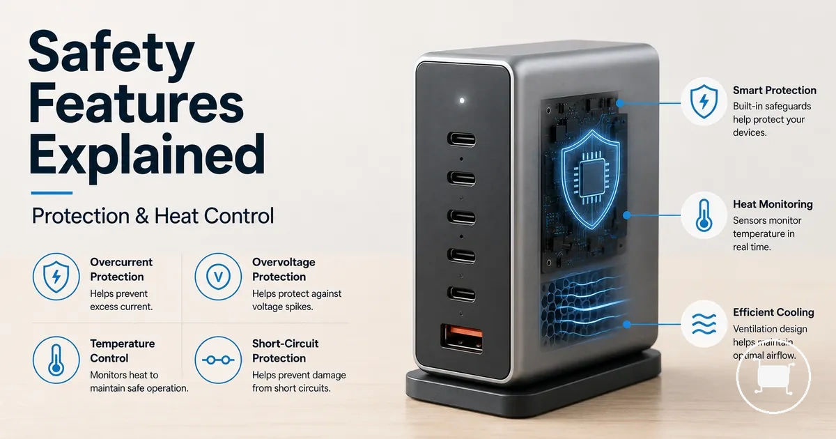
Safety features reduce risk, but they do not guarantee safe outcomes. Overvoltage protection, overcurrent protection, short-circuit protection, and over-temperature protection can help limit common fault conditions, but actual safety still depends on standards compliance, build quality, cable quality, USB-IF certification, device negotiation, and correct use. Safe fast charging, certified charging, and safe user behavior are related, but none of them replaces the others.
A safer charger is evaluated as a system, not as a single label or feature.
The next protection layer is electrical and thermal control, where the charger manages unsafe voltage, excess current, short-circuit conditions, and heat before those risks move further through the cable path.
How safety features protect a multiport USB-C charger and connected devices
Charger safety features are built-in protections that reduce risk by monitoring power delivery and responding to unsafe conditions before they reach connected devices. These safeguards help manage voltage, current, and heat as power moves through the charger. The protection path extends from the charger and USB-C port through the cable path to the connected device.
How safety features protect a multiport USB-C charger and connected devices is easier to visualize when the protection path is viewed as a connected system. The diagram below shows where protection functions may act across the charger, cable path, and connected devices to support risk reduction.
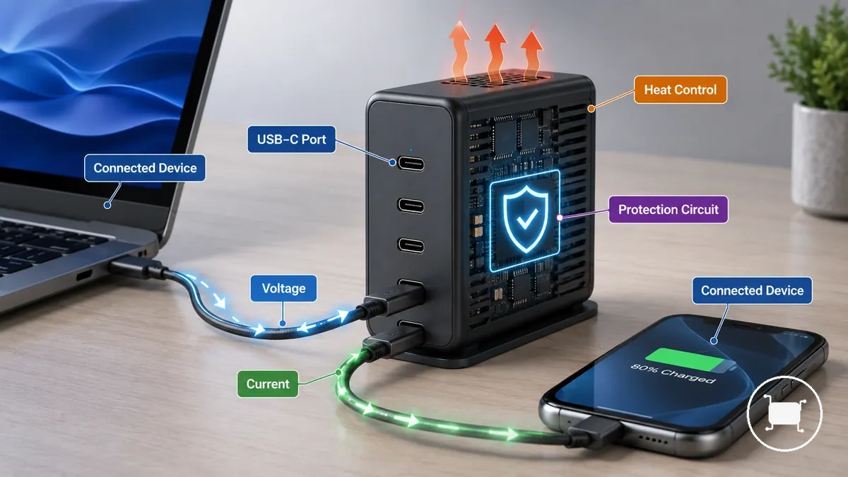
Electrical risk control begins when a protection circuit monitors voltage and current at the charger or USB-C port. If an unsafe condition is detected, the charger may apply a controlled response that helps reduce the likelihood of excessive power reaching connected devices.
Heat and load control help manage thermal stress that can develop during charging. When heat increases beyond expected operating conditions, built-in protection may adjust charger behavior to support reduced risk across the charger and connected devices.
- An electrical fault can trigger a controlled response that helps limit exposure to abnormal voltage or current.
- Heat buildup can be managed through safeguards that respond to rising thermal conditions.
- A cable mismatch can increase risk along the cable path when cable quality or connector condition is unsuitable.
- Charging negotiation helps align power delivery between a USB-C port and a connected device before charging continues.
- User conditions still matter because protection limits depend on compliant design, correct use, and equipment condition.
Built-in protection supports risk reduction, but it works alongside compliant design, correct use, and safe charging habits rather than replacing them. Questions about whether multi-device charging is safe often depend on those conditions as much as the protection features themselves. For broader context, see the multiport USB-C charger guide.
Electrical protection against unsafe voltage and current
Electrical protection limits abnormal electrical conditions before they create unnecessary risk for charger circuitry or connected devices. A protection circuit monitors power delivery and may respond when operating conditions move outside expected limits. These safeguards address unsafe voltage, unsafe current, surge, and short-circuit risk through different protection paths.
Electrical protection against unsafe voltage and current is easier to understand when fault paths are separated by the condition they address. The diagram below organizes voltage faults, current faults, surge events, and ESD events before the table maps each condition to a likely response.
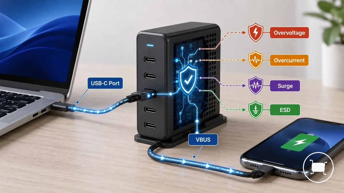
VBUS carries power between the USB-C port and the connected device, making it a common location for monitoring abnormal voltage and current behavior. Overvoltage protection focuses on unsafe voltage conditions, while overcurrent protection and short-circuit protection address excess current and fault conditions that may increase heat risk. Surge protection and ESD protection help manage transient spikes that can reach a USB-C port or connected circuitry.
The table below maps electrical fault types to likely protection responses and the risk each response is intended to reduce.
| Entity/part | Unsafe condition | Protection response | Risk reduced |
|---|---|---|---|
| VBUS | Unsafe voltage | Overvoltage protection may limit or interrupt power flow | Stress on connected circuitry |
| USB-C port | Unsafe current | Overcurrent protection may trigger cutoff behavior | Excess heat and electrical load |
| Cable/device fault path | Short circuit | Short-circuit protection may shut down power delivery | Fault-related damage risk |
| Surge event | Transient spike | Surge protection may absorb or redirect part of the event | Voltage-related stress |
| ESD event | Electrostatic discharge | ESD protection may reduce exposure to the discharge | Port safety risk |
A practical example is a defective cable or device creating a fault condition that causes abnormal current flow, where protection behavior may reduce risk by limiting power delivery. Output ratings and protection behavior should be evaluated together because charger responses can vary by design and fault type. For broader context, see power output and safety.
Overvoltage protection
Overvoltage protection is the safeguard that reacts when a voltage level rises beyond the expected charging range. It helps limit abnormal voltage exposure at the USB-C port before excess voltage reaches connected circuitry. The primary risk is voltage beyond the expected charging range on the VBUS path.
Overvoltage protection is easier to understand when viewed at the point where voltage is monitored and controlled. The annotated example below shows how the USB-C port and VBUS path can be positioned between an abnormal voltage source and the connected device, with a protection cutoff acting as a local safeguard.
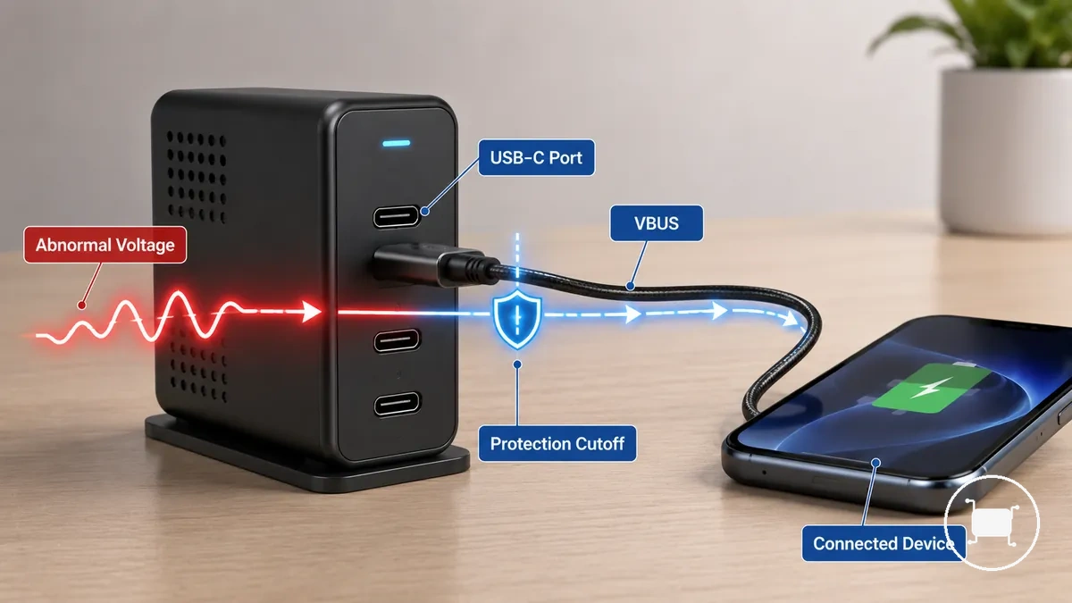
Overvoltage protection monitors the VBUS voltage level and compares it with the expected power negotiation state. If a defective charger, defective cable, or another fault condition creates abnormal voltage, a protection circuit may trigger voltage cutoff behavior or a voltage clamp response. The exact trigger point and cutoff behavior can vary by charger design, negotiated voltage, specification context, and operating conditions, so protection should not be treated as an absolute guarantee.
Overcurrent and short-circuit protection
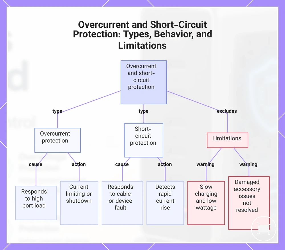
Overcurrent and short-circuit protection are safeguards that limit excessive current flow or interrupt a fault path before it creates unnecessary stress on charging components. Overcurrent protection responds to excess current caused by a high port load, while short-circuit protection responds to a direct fault path created by a cable fault or device fault. The key distinction is excess load versus a fault path.
Overcurrent protection compares port load against a current threshold and may apply current limiting or shutdown behavior when demand exceeds expected operating conditions. Short-circuit protection focuses on detecting a fault path that can allow current to rise rapidly through a cable fault or device fault. Both protections can help reduce heat risk and component damage, although the exact shutdown behavior and recovery process may vary by charger design and operating conditions.
In a multi-device charging scenario, a high port load does not automatically indicate a short circuit. Overcurrent protection addresses overload conditions, while short-circuit protection addresses fault-related current flow. These safeguards help manage current-related risk, but they do not fix slow charging, compensate for low available wattage, or resolve all damaged-accessory problems.
This chart shows the two main types of current protection, what each responds to, how they act, and what they do not address.
Surge and ESD protection around USB-C ports
Surge and ESD protection around USB-C ports are safeguards that help reduce exposure to brief electrical spikes at the connector. Surge protection focuses on a transient spike, while ESD protection focuses on electrostatic discharge that can occur at or near a USB-C connector. Both protections address short-duration electrical events rather than continuous overload conditions.
| Event type | What the protection reduces |
|---|---|
| Surge | Exposure to a transient spike that may reach the USB-C port |
| ESD | Exposure to electrostatic discharge that may affect internal circuits |
Surge protection and ESD protection use a protective component near the USB-C port to help manage brief electrical events before they reach sensitive internal circuits. When a transient spike or static discharge occurs, the protective component may reduce the electrical stress reaching the USB-C connector and related internal circuits. The exact response can vary by charger design and event conditions, but the protection remains focused on port safety rather than continuous power-load control.
Heat control and over-temperature protection
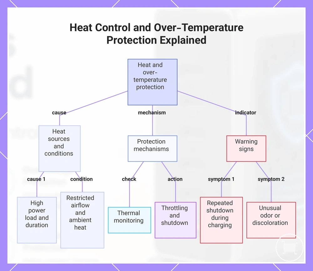
Heat control and over-temperature protection are safety functions that help a multiport USB-C charger operate within safer limits when charging devices under normal or high load. A charger can generate heat during power conversion and delivery, especially as load level increases across multiple ports. These protections help manage operating heat, but they do not guarantee an exact temperature under every condition.
Heat can come from the charging electronics, the enclosure, connected devices, and sustained power delivery. A higher load level, a compact enclosure design, a long charging session, or a high-wattage charging scenario can increase operating warmth. Environmental conditions such as restricted airflow or elevated ambient temperatures can also influence how much heat a GaN charger retains during use.
Thermal monitoring tracks temperature conditions inside the charger and helps determine when protective action may be needed. When operating heat rises beyond intended conditions, thermal throttling may reduce power delivery to limit additional heat generation. In some situations, shutdown behavior may occur to reduce thermal stress, while recovery can depend on charger design, load level, ventilation, and surrounding conditions.
Expected warmth and potential risk signals are not the same. Heat control is designed to manage normal operating heat, while the following signs may indicate conditions that deserve closer attention:
- Expected warmth during normal charging, especially under a higher load level.
- Blocked ventilation or restricted airflow around the charger enclosure.
- Noticeable heat at a cable or connector that may depend on connection quality or charging conditions.
- Repeated shutdown behavior during similar charging sessions.
- Unusual smell or visible discoloration around the charger or connector area.
- Use in confined, insulated, or unusually warm environments with limited ventilation.
Heat control and over-temperature protection help manage operating heat, but persistent overheating symptoms can require separate evaluation. For more detailed guidance on the difference between managed operating warmth and ongoing thermal concerns, see overheating and heat protection.
This chart shows the main causes of heat buildup, the protection mechanisms used, and the warning signs that indicate potential issues with a multiport USB-C charger.
Normal operating heat versus unsafe overheating
Normal operating heat can be expected during charging, while unsafe overheating deserves caution when heat warning signs appear. Surface warmth often increases with load and charging duration, especially during higher-power use. Warmth becomes a concern when it is accompanied by conditions that may indicate unsafe overheating rather than expected warmth.
Normal operating heat is typically experienced as surface warmth that varies with load, duration, charger design, and environmental conditions. Unsafe overheating may be associated with warning signs such as unusual smell, discoloration, repeated shutdown behavior, persistent cable heat, connector heat, or unexpected device response during charging. Any single sign does not confirm a specific fault, but these conditions can suggest that excessive heat may require closer attention.
The distinction between normal operating heat and unsafe overheating is based on interpreting visible or felt heat warning signs rather than diagnosing the exact cause.
Thermal monitoring and shutdown behavior
Thermal monitoring and shutdown behavior are protective functions that help limit continued operation when charger heat approaches a thermal limit. A temperature sensor and control circuit monitor heat conditions and can respond when additional heat reduction may be needed. Depending on charger design, thermal monitoring may lead to thermal throttling, reduced output, or shutdown behavior.
User-visible effects can vary by charger model and charging conditions. When thermal monitoring detects elevated heat, reduced output may slow charging, or a temporary shutdown may interrupt charging until a restart condition is met. In some cases, a charging interruption can resemble a charging failure, but recovery timing and restart condition behavior may depend on charger design, heat level, and surrounding conditions.
GaN charger efficiency and thermal safety limits
A common claim is that a GaN charger is safer simply because it runs cooler. The safer interpretation is that GaN charger efficiency is associated with lower wasted heat as part of a charger's thermal design, but efficiency alone does not determine safety. GaN can improve efficiency and support compact design goals, but it does not replace safety design or protection circuits.
GaN charger design is often associated with higher power density, allowing more power capability within a smaller enclosure size. However, higher power density can also increase heat concentration inside a compact charger, so thermal performance may still depend on load conditions, enclosure design, temperature control, and thermal limits. Lower wasted heat does not eliminate heat generation during normal operation.
Certification, build quality, thermal design, and protection circuits remain important safety factors alongside efficiency. A gallium nitride charger should be viewed as one design attribute that may contribute to thermal performance rather than as a standalone indicator of safety.
Safe fast charging during power negotiation
Safe fast charging depends on power negotiation between the charger and the connected device rather than the charger delivering maximum power at all times. In USB-C PD, the charger provides available source capability while the connected device requests a suitable charging profile. Safe fast charging is negotiated, not forced.
Power negotiation involves the charger, connected device, fast-charging protocol, and cable rating working together to determine a negotiated output. The connected device requests a requested voltage and current limit, the charger evaluates whether that power level can be provided, and the cable rating may influence how much current can be carried safely. The resulting power contract can vary by protocol support, device compatibility, port state, and cable characteristics.
The table below shows how each charging element contributes to safe output during charging negotiation.
| Entity/part | Attribute/condition | Value or request | Effect on safe charging |
|---|---|---|---|
| Charger | Source capability | Available power levels | Sets the range of power that may be offered |
| Connected device | Sink request | Requested voltage and current limit | Determines the power level the device may accept |
| Cable | Cable rating | Supported current capacity | Can influence safe current delivery |
| Protocol | Protocol support | USB-C PD or other fast-charging protocol | Enables charging negotiation and power matching |
| Port state | Operating condition | Current charging status | May affect the negotiated output available |
Understanding protocol support and safe charging helps clarify why actual charging performance depends on negotiation rather than charger wattage alone. Power negotiation can reduce charging-related risk by matching charger capability, device requests, and cable conditions, but it cannot compensate for damaged cables, faulty connectors, or non-compliant hardware.
Voltage and current negotiation in USB-C PD charging
Voltage and current negotiation in USB-C PD charging is the mechanism that helps a charger match device charging limits through a negotiated output. USB-C PD uses communication between the charger and the connected device before higher charging levels are applied. The negotiation model is based on source capability and sink request.
During PD negotiation, the charger presents source capability information, the connected device sends a sink request, and a power contract is established for an appropriate voltage level and current limit. The resulting output may vary according to device limits and charger capability, while fallback behavior can occur when a requested power level is unavailable or unsupported. This approach can support compatibility and safer charging by aligning requested power with available output rather than relying on a fixed power level.
Cable quality and power-rating limits
Cable quality and power-rating limits affect whether safe fast charging can operate as intended because the USB-C cable is part of the charging path. Charger protections and charging negotiation may depend on the cable carrying power within its intended limits. The cable is part of the safety path.
A USB-C cable's power rating, current carrying limit, and connector condition can influence charging behavior and mismatch risk. A rated cable that matches the charging requirement may support negotiated power delivery more effectively, while a damaged cable or poor connector condition can contribute to heat at the connector or charging instability. For higher-power charging scenarios, an e-marker may be relevant because charging capability can depend on cable design and supported limits.
The checklist below can help identify cable-related conditions that may affect charging safety and negotiation, especially when higher power levels are involved.
- Verify that the USB-C cable power rating is appropriate for the intended charging level.
- Inspect connector condition for wear, looseness, contamination, or visible damage.
- Check for unusual heat at the connector during charging, particularly under higher power demand.
- Confirm whether an e-marker may be relevant when using a high-power cable or charging setup.
- Watch for mismatch risk between charger capability, cable limit, and connected device requirements.
- Consider replacement when a damaged cable shows persistent wear, connection issues, or recurring heat symptoms.
Safety certifications and compliance markings
Safety certifications and compliance markings are external trust signals that help evaluate charger claims and product traceability. They can support confidence in documented specifications and compliance-related statements, but they do not replace safe charger design, proper use, or independent evaluation. These markings are trust signals rather than absolute guarantees.
USB-IF participation and a certified USB logo can support interoperability-related claims within a compliance program, while electrical safety markings can support claims that a product has undergone a relevant evaluation process. A charger label, manufacturer identity, and stated power rating provide additional verification signals that help distinguish documented specifications from marketing claims.
The checklist below focuses on evaluating the quality of supporting evidence behind charger claims. It helps verify whether compliance labels, traceability information, and power-related statements are presented clearly and consistently.
- Check whether a certified USB logo or USB-IF-related claim is displayed clearly and consistently.
- Verify that manufacturer identity is visible on the charger label, product body, or packaging.
- Review the stated power rating and input/output information for clarity and consistency.
- Look for electrical safety markings that are legible and identifiable.
- Confirm whether cable power information is provided when higher-power charging claims are presented.
- Compare marketing wording with specific technical details rather than relying on broad promotional statements.
- Check whether packaging or product information provides traceability details that help identify the charger.
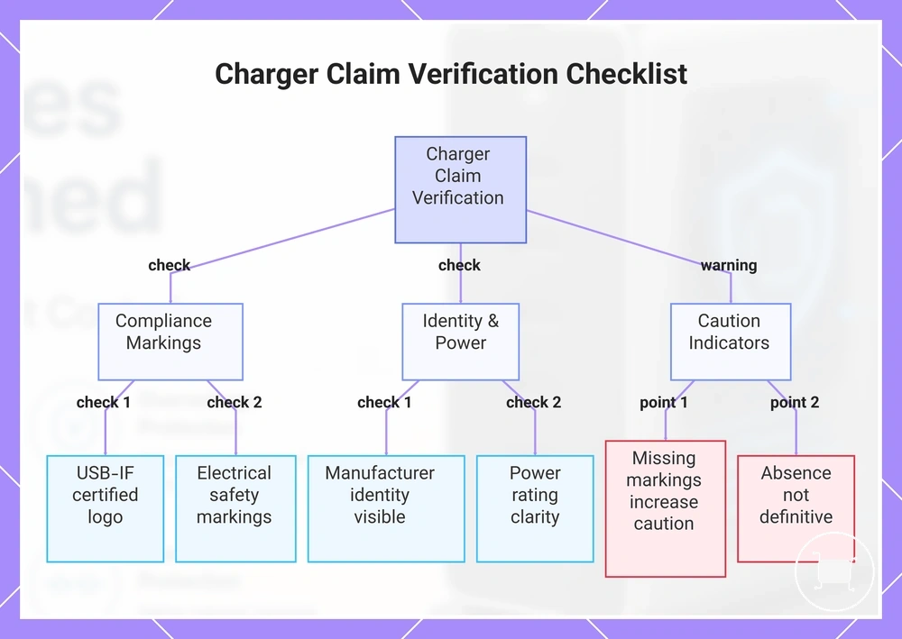
Missing, unclear, or inconsistent compliance markings should increase caution when evaluating a charger, particularly when manufacturer identity, charger label details, or power rating information cannot be verified easily. However, the absence of a specific marking alone does not automatically determine whether a charger is safe, compliant, or authentic.
This chart organizes the main categories of checks to verify charger claim evidence, including compliance markings, identity and power details, and caution indicators.
USB-IF certification and logo checks
USB-IF certification and logo checks are a way to assess standards-related claims about USB products and their stated capabilities. USB-IF certification indicates participation in a compliance program that includes compliance testing for specific requirements. As a result, USB-IF certification can serve as a confidence signal for compliance and interoperability.
A certified USB logo, USB-IF mark, product listing, power capability label, or cable label may help support a certified charger or cable claim when presented clearly and consistently. These checks can improve user confidence, but the presence or absence of a certification mark alone does not determine whether a specific charger or cable is safe or suitable for every use case.
Electrical safety markings and manufacturer claims
Electrical safety markings and manufacturer claims help users evaluate whether charger protection claims are supported by identifiable product information. Clear label details provide stronger verification signals, while vague statements provide less supporting evidence. A safety mark is distinct from a marketing phrase.
- Safety mark: Usually appears with a charger label, rated input, rated output, or compliance labels that support product traceability.
- Marketing phrase: May reference protection claims such as overvoltage, overcurrent, or temperature control without providing supporting label details.
Rated input, rated output, manufacturer name, and traceability details are practical claim-check signals. When this information is visible and consistent on the charger label or rating label, users can more easily compare stated specifications with manufacturer claims. Clear manufacturer identification also supports product traceability and helps distinguish documented specifications from vague claims.
Extra caution may be appropriate when protection claims are broad but supporting information is unclear or missing. The meaning of compliance labels can vary across markets and contexts, so label clarity, manufacturer name visibility, and traceability are often more useful trust signals than marketing wording alone.
Safety features to compare before trusting a charger
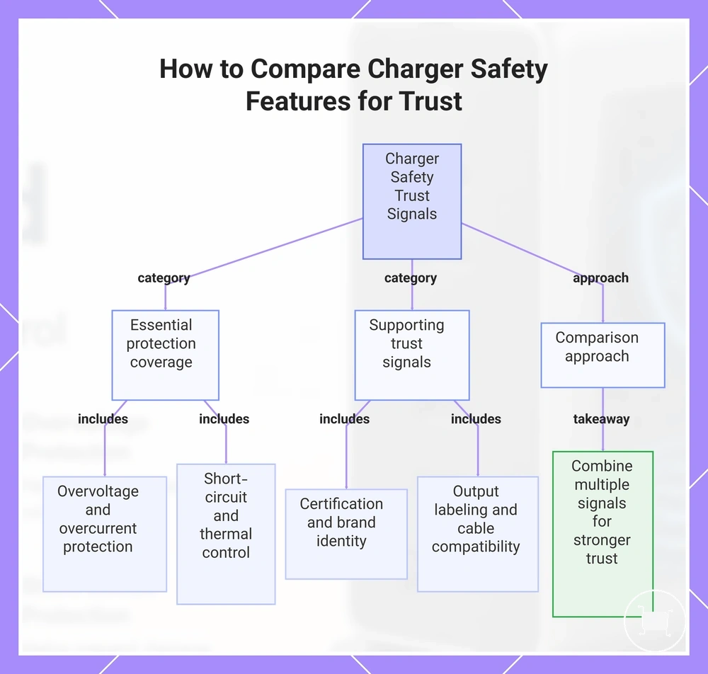
Safety features to compare before trusting a charger depend on protection coverage, certification, and realistic use conditions rather than a single product claim. Trust is usually stronger when multiple verification signals support each other. Multiple signals should be compared together before drawing conclusions about charger suitability.
Essential protection coverage includes overvoltage protection, overcurrent protection, short-circuit protection, and thermal control. These safety features address different operating conditions, so protection coverage is generally more meaningful when these protections are considered together rather than as isolated claims.
Supporting trust signals include certification, brand traceability, manufacturer identity, output labeling, and cable compatibility. Clear output labeling, visible manufacturer information, and identifiable certification details can help users compare stated specifications with product claims. Cable compatibility may also influence safe use conditions because charging behavior can depend on cable power rating and connected device requirements.
The checklist below focuses on decision signals that help distinguish essential protections from weaker marketing wording.
- Overvoltage protection: Look for a clear protection claim; supports evaluation of protection coverage.
- Overcurrent protection: Verify that the protection is identified specifically rather than implied.
- Short-circuit protection: Check whether fault-related protection is listed as part of the safety features.
- Thermal control: Look for evidence of heat-management features rather than performance-focused wording alone.
- Certification: Check for identifiable certification information that supports product verification.
- Brand traceability: Confirm that manufacturer identity and traceability details are available.
- Output labeling: Review rated output information for clarity and consistency.
- Cable compatibility: Compare cable power rating and connected device requirements with the intended charging setup.
These criteria help compare trust signals without treating any single feature as conclusive proof of safety. For a broader evaluation process that applies these criteria in practice, see safety checks before buying.
This chart shows the main categories of safety signals to evaluate when comparing chargers, including essential protections, supporting trust indicators, and the principle of combining multiple signals.
What built-in charger protections cannot control
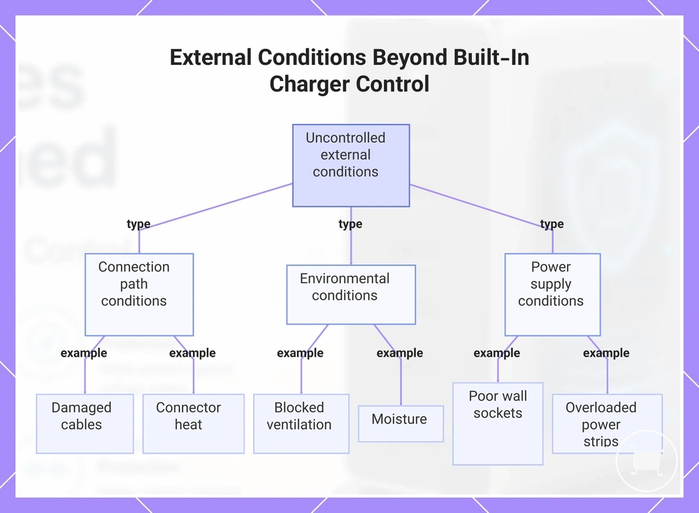
Built-in charger protections reduce risk, but they cannot control every external condition that affects charging safety. Charger protection operates within the charger, while many remaining risks originate from connected accessories, the charging environment, or user-controlled conditions. External conditions include damaged cables, blocked ventilation, poor wall sockets, counterfeit markings, moisture, overloaded power strips, and unsafe storage conditions.
Built-in charger protections have clear protection limits when charging issues originate outside the charger. Damaged cables, worn connectors, connector heat, or cable mismatches can create conditions that charger protection may not fully control because the source of the issue exists within the connection path rather than the charger itself.
Environmental and power-supply conditions also remain outside direct charger control. Blocked ventilation can restrict heat dissipation, while poor wall sockets, overloaded power strips, moisture exposure, and unsafe storage conditions may introduce risks that depend on the charging setup and surrounding environment. Not every external condition creates the same level of risk, but each remains outside the scope of built-in charger protections.
The checklist below highlights common external conditions that built-in charger protections cannot fully control.
- Damaged cables: Cable damage can create charging problems that charger protection may not fully prevent.
- Connector heat: Heat at the connector can depend on cable condition, fit, contamination, or wear outside the charger.
- Blocked ventilation: Charger protection cannot fully compensate for restricted airflow around the charger.
- Poor wall sockets: Socket condition remains an external factor that charger protection may not fully manage.
- Moisture: Exposure to moisture can create operating conditions outside the charger's intended environment.
- Overloaded power strips: Shared electrical loads can create external conditions beyond direct charger control.
- Counterfeit markings: Product markings alone may not verify actual protection coverage or product authenticity.
These boundaries clarify the difference between charger-controlled protections and user-controlled risks. Following safe charging habits can help address conditions that remain outside the scope of built-in charger protections without treating safety features as a substitute for safe use.
This chart shows the main external conditions that built-in charger protections cannot control, grouped by connection, environmental, and power supply risks.